Measure Distance Using Ultrasonic Sensor

Esp01

Nodemcu wifi controlled bot

Latest Posts

Saturday, May 15, 2021

IoT Controlled LED using Blynk and ESP8266 (NodeMCU)

ManiTesla.tech

                                        Getting to Know NodeMCU Board


It is an Open-source, Interactive, Programmable, Low cost, Simple, Smart, WI-FI-enabled board that may assist you to create IoT projects with ultra-fast prototyping.

The Development Kit supported ESP8266, integrates GPIO, PWM, IIC, 1-Wire, and ADC beat one board. Power your development within the fastest way with NodeMCU Firmware! . 

Blynk library link:https://github.com/blynkkk/blynk-library/releases


                                                Getting to Know Blynk

blynk_server_working

Blynk may be a Platform with iOS and Android apps to regulate Arduino, Raspberry Pi and therefore the likes over the web .

Blynk was designed for the web of Things. It can control hardware remotely, it can display sensor data, it can store data, vizualize it and do many other cool things.

It's a digital dashboard where you'll build a graphic interface for your project by simply dragging and dropping widgets. It's really simple to line everything up and you will start tinkering in but 5 mins. Blynk isn't tied to some specific board or shield. Instead, it's supporting hardware of your choice. Whether your Arduino or Raspberry Pi is linked to the web over Wi-Fi, Ethernet or this new ESP8266 chip, Blynk will get you online and prepared for the web Of Your Things.

How does it work?

There are three major components within the platform:

Blynk App- allows to you create amazing interfaces for your projects using various widgets we offer.

Blynk Server - liable for all the communications between the smartphone and hardware. you'll use our Blynk Cloud or run your private Blynk server locally. It’s open-source, could easily handle thousands of devices, and may even be launched on a Raspberry Pi.

Blynk Libraries - for all the favored hardware platforms - enable communication with the server and process all the incoming and outcoming commands.

                                    Setting Up Blynk With Arduino IDE

Setting_Up_Blynk_With_Arduino_IDE
                                          
This blynk app has set of library files which need to be included within the Arduino IDE environment before the project is executed
1. Follow the link to put in libraries

2. Once the Zip file is downloaded,extract it and individually copy all the folder to your libraries folder of your arduino

3. Once done just open Arduino IDE and attend Sketch-> Include libraries and you'd see blynk within the menu

4. If you see that then libraries are included successfully
*Now it's time to incorporate the board configuration within the Arduino IDE

Board configuration?

Lets start. within the Arduino IDE attend File->Preferences
Now Copy the below link and paste it within the Additional Boards Manager Url text box
Restart the Arduino IDE then .
Now after restarting the Arduino IDE , attend Tools->Boards and choose Node MCU board , mine was version 0.9 

                                             Setting Up Blynk

1. First install the Blynk app from google play store then check-in 

2. Click on New Project and you'll get a screen

*Enter the name of your project, I even have given it as iot led

*Then Select the Board as NODEMCU and then you'll recieve the authentication token no to your email id.

*And then Finally click on to the create button

3. Now you'll get your dashboard screen. Just click on the button "+" on the upper corner to feature widgets for your project.

4. During this project we add a button then configure its settings as Digital D4 pin.(Refer Screen Shots)

5. Its your choice you'll either have the button set as push type or as a switch
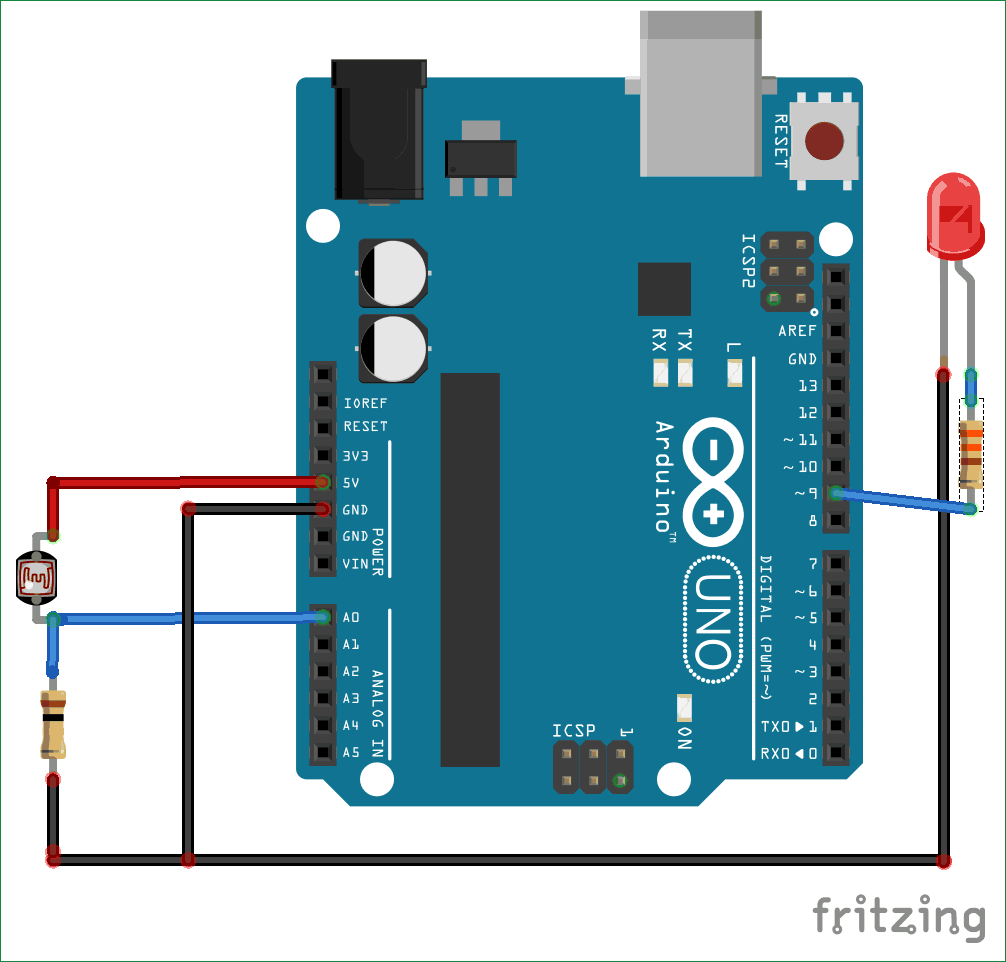
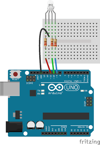
6. Then label the Button as ON and OFF within the settings 

                                                  Circuit Diagram:

Circuit_diagram

1. The connection is pretty simple just connect the Led to D4 pin via 330/220Ohm resistor. (refer to the diagram) 

                                             Uploading the Code

                                 Uploading the code

1.Connect your Esp8266 Wifi to your PC
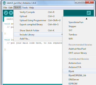
2. Open Arduino IDE

3. Then attend File->Eamples->Blynk-Boards_Wifi->Esp8266Standalone

(Refer screen shot)

4. Select the right board (NodeMCU 1.0) and therefore the com port from the Tools Menu

Finally Save the file and Press Upload

                                                 Final Execution


1. After uploading the code

2. Open the Blynk app in the Phone

3. Let it connect to the internet

4. Then you would see your dashboard with a button

5. Press Play button on the top most right corner of the app

6. Then Alas!! Press the Button and you would see the LED Turn ON!!!:)


Sunday, April 25, 2021

How PIR work | PIR motion sensor with and without arduino

ManiTesla.tech

 Hello My name is Manitesla i'll be teaching you guys how to use PIR sensor. HC-SR501 PIR sensor has three output pins VCC, Output and Ground as shown within the diagram below. It has a built-in transformer so it are often powered by any DC voltage from 4.5 to 12 volts, typically 5V is employed . Other than this, there are a few options you've got together with your PIR. Let’s check them out.

One of the explanations of HC-SR501 PIR sensor being extremely popular is that the incontrovertible fact that HC-SR501 may be a very versatile sensor that's pretty capable all on its own. And by interfacing it to some microcontrollers like an Arduino you'll expand upon its versatility even further. For our first experiment we'll use the HC-SR501 on its own for instance how useful it's by itself.


Pir Sensor

The wiring for this experiment is very simple. Batteries are connected across VCC and GND of the sensor and alittle Red LED is connected to the output pin through a 220Ω current limiting resistor. That’s it!

Now when the PIR detects motion, the output pin will go “high” and light up the LED!

Remember once you power up the circuit you would like to attend 30-60 seconds for the PIR to acclimatize to the infrared energy within the room. During that time the LED may blink a little. Wait until the LED is off then move around ahead of it, waving a hand, etc, to ascertain the LED light up!


Pir without arduino

Wiring – Connecting PIR Sensor to Arduino UNO

Now that we've an entire understanding of how PIR sensor works, we will begin hooking it up to our Arduino!
Connecting PIR sensors to a microcontroller is basically simple. The PIR acts as a digital output so all you would like to try to to is listen for the output pin to flip HIGH (Motion Detected) or LOW (Not Detected). Power the PIR with 5V and connect ground to ground. Then connect the output to a digital pin #2.
You will want to line the jumper on the HC-SR501 to the H (Retriggering) position for this to figure correctly. You’ll also got to set the TIME to the minimum of three seconds, turn the TIME potentiometer as far counterclockwise because it will go. Set the sensitivity anywhere you wish , set it to midpoint if you're unsure .


Pir with arduino

Arduino Code:

int ledPin = 13;                // choose the pin for the LED
int inputPin = 8;               // choose the input pin (for PIR sensor)
int pirState = LOW;             // we start, assuming no motion detected
int val = 0;                    // variable for reading the pin status
 
void setup() {
  pinMode(ledPin, OUTPUT);      // declare LED as output
  pinMode(inputPin, INPUT);     // declare sensor as input
 
  Serial.begin(9600);
}
 
void loop(){
  val = digitalRead(inputPin);  // read input value
  
  if (val == HIGH)	// check if the input is HIGH
  {            
    digitalWrite(ledPin, HIGH);  // turn LED ON
	
    if (pirState == LOW) 
	{
      Serial.println("Motion detected!");	// print on output change
      pirState = HIGH;
    }
  } 
  else 


Sunday, December 13, 2020

Using LDR sensor with Arduino | Arduino Day/Night Sensor Circuit using LDR (With daigram)

ManiTesla.tech

Hello everyone I'm Manitesla .In this post, you will learn how to use an LDR or Light Dependent resistor to turn on and off another circuit or a LED.

This project would help you in understanding how automatic day/ night activated LEDs work. Do you guys want to know how whenever a room gets dark, a light bulb automatically turns ON and the darkness disappears. In this very simple project, ill teach you everything you need to know to make your own day/light sensor.


Ldr working


A LDR (Light Dependent Resistor) or a photo resistor is a photo conductive sensor. It is a variable resistor and changes its resistance varies with light intensity. It’s resistance decreases with the intensity of light.

Circuit Diagram:


arduino ldr connection


Arduino Code:

int led= 9;
void setup() {

Serial.begin(9600);

pinMode(led, OUTPUT);

pinMode(A0, INPUT);

}

void loop() {

int val = analogRead(A0);
Serial.println(val);
if (val <= 150) {

digitalWrite(led, HIGH);

} else { digitalWrite(led, LOW);
} } 

Thursday, November 19, 2020

How to use RGB Led with arduino to produce 16 million colours (Full detailed tutorial)

ManiTesla.tech
Hy everyone i'm your Manitesla.In this post you will learn how to work with RGB LED’s. This Post and my video shows you how to connect a Common Cathode RGB LED  to an Arduino uno. Below i have given code  for your reference, you try not to just copy and paste it. In order to really learn, you need to type it in for yourself, and then find and debug your mistakes. 
                                                       
RGB led

Using an RGB led we can generate any color by controlling the brightness of the individual Red, Green and Blue LEDs. The following image shows a few possible colors of light that can be generated using an RGB LED.

                             PWM Diagram
 An  important point is that you should  make sure that you connect the Red, Green and Blue Anodes of the RGB LED to three PWM supported pins of Arduino since we are using a common cathode rgb led

Circuit Diagram:

                                         RGB Colour wheel
Code:
Circuit diagram
Arduino
1
2
3
4
5
6
7
8
9
10
11
12
13
14
15
16
17
18
19
20
21
22
23
24
25
26
27
28
29
30
31
32
33
34
35
36
37
38
39
40
41
42
43
44
45
46
47
48
int redPin=11;
int greenPin=10;
int bluePin=9;

void setup() {
  // put your setup code here, to run once:
Serial.begin(9600);
pinMode(redPin,OUTPUT);
pinMode(greenPin,OUTPUT);
pinMode(bluePin,OUTPUT);
}
 
void loop() {

  // put your main code here, to run repeatedly:

//red
  analogWrite(redPin,255);
  analogWrite(greenPin,0);
  analogWrite(bluePin,0);
//green
  analogWrite(redPin,0);
  analogWrite(greenPin,255);
  analogWrite(bluePin,0);
//blue
  analogWrite(redPin,0);
  analogWrite(greenPin,0);
  analogWrite(bluePin,255);
//magenta
  analogWrite(redPin,255);
  analogWrite(greenPin,0);
  analogWrite(bluePin,255);
//yellow
  analogWrite(redPin,255);
  analogWrite(greenPin,255);
  analogWrite(bluePin,0);
//cyan
  analogWrite(redPin,0);
  analogWrite(greenPin,255);
  analogWrite(bluePin,255);
//white
  analogWrite(redPin,255);
  analogWrite(greenPin,255);
  analogWrite(bluePin,255);


}


Owner

  • Manitesla Youtuber
  • Manikant Savadatti Electronics Engineer